Once a material is on the drawing, the shop floor asks two things: whether it will run cleanly, and how many trials it will take. The answer sits further upstream than most designers expect: how forgiving the material’s processing window is. That window is the range a process parameter can move through before the part changes. A wide one absorbs temperature drift. A narrow one turns ordinary variation into extra trial rounds and schedule risk.
So the numbers come first. The chart below covers the plastics that appear in most design reviews.
Processing Windows for Common Plastics
Melt temperature here means the actual temperature of the plastic melt at the nozzle, not the setpoint shown on the machine controller. The ranges below are typical for each material family.
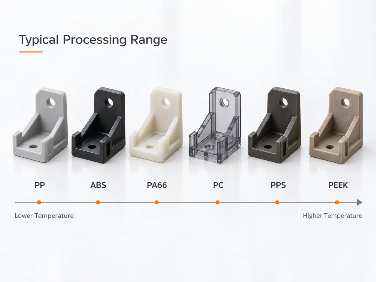
A processing window covers more than temperature. Pressure, injection speed, hold time and cooling each have their own limits, and the mold and machine have to satisfy all of them at the same time. The numbers in this chart cover the temperature side of that window, which is the part your injection molding material selection decides.
| Material | Melt temperature, typical (°C) | Mold temperature, typical (°C) |
|---|---|---|
| ABS | 200–260 | 40–80 |
| HDPE | 200–280 | 20–60 |
| HIPS | 180–260 | 20–60 |
| PA6 | 230–280 | 60–100 |
| PA66 | 260–300 | 60–100 |
| PBT | 240–270 | 60–100 |
| PC | 280–320 | 80–120 |
| PC-ABS | 240–280 | 60–90 |
| PMMA | 210–250 | 50–80 |
| POM | 190–230 | 60–120 |
| PP | 200–280 | 20–80 |
| TPE / TPU | 180–230 | 20–50 |
High-temperature grades sit in a different range entirely, and their windows are narrower. For example, PEEK injection molding requires substantially higher melt and mold temperatures than general-purpose plastics.
| Material | Melt temperature, typical (°C) | Mold temperature, typical (°C) |
|---|---|---|
| PPS | 300–340 | 120–160 |
| PEEK | 350–400 | 150–200 |
| LCP | 280–340 | 80–120 |
A few notes before you use either table:
- These are typical published windows for the family. Your resin supplier’s processing guide governs, and it commonly narrows the range further, especially for filled and modified grades.
- A range is a boundary, not a target. Where you sit inside it depends on wall thickness, flow length and surface requirements.
If your material is not listed here, treat the nearest material in the same family as a starting point rather than an answer.
Each material gets two numbers in that table, and they are not interchangeable. They do different jobs in the process.
Two Numbers, Two Different Jobs
What it controls. Melt temperature sets viscosity, so it decides whether the melt reaches thin walls and fine detail before it freezes. Mold temperature sets cooling rate, which drives surface gloss, internal stress and dimensional stability.
Where it is set. Melt temperature is set through barrel temperatures, screw speed and back pressure. Mold temperature is set through the temperature controller and the cooling circuits in the tool.
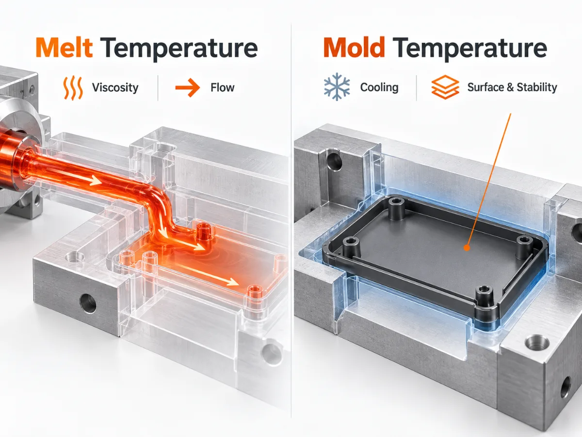
The most common misreading is treating mold temperature as if it were melt temperature, which makes an ordinary process look far too cold. They trade off against each other, but they do not substitute for each other.
Both columns matter when you read the chart, but for a material decision the column to watch is melt temperature. Running at the lower end of that range buys shorter cooling and less risk of degradation. The upper end buys flow for thin sections. That is a choice, not a default.
Melt temperature is also the number that gets reported differently depending on where you look.
Which Temperature Number You Need
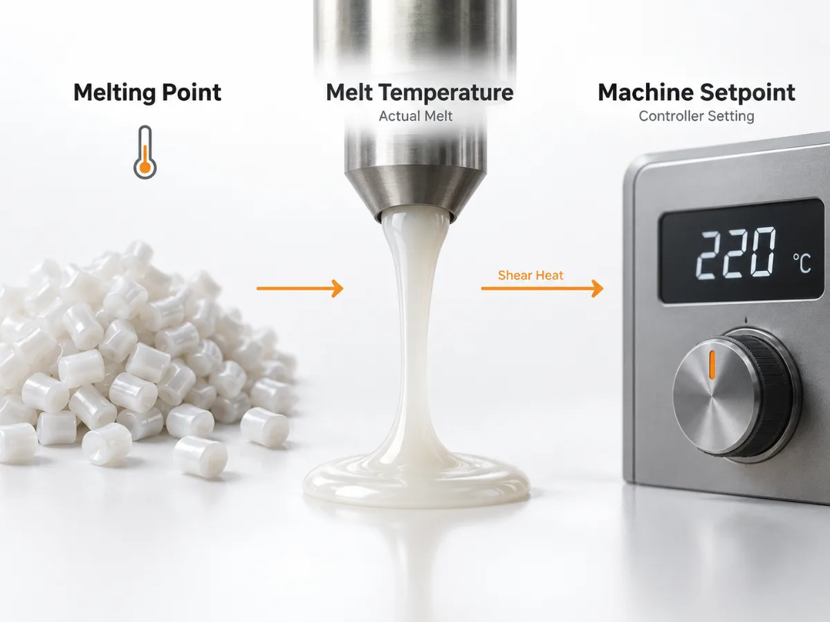
The same material will show you three values, and they are not contradicting each other. Each one answers a different question.
| Number | What it describes | What to use it for |
|---|---|---|
| Melting point (often quoted in a TDS) | The point where the material becomes fluid enough to flow | Understanding the material itself. It is not a processing temperature. |
| Melt temperature (the column in the chart above) | The actual temperature of the melt at the nozzle | Judging whether the process is feasible and how much window you have. |
| Machine setpoint (what the shop floor reports) | The value the controller is set to, based on heater bands and screw parameters | Aligning with your molder. Not a substitute for the supplier’s range. |
The gap between the second and third rows is the one that causes confusion, and it has a physical reason behind it. A large share of the energy that melts the plastic comes from shear and back pressure inside the screw, not from the heater bands. So the number on the screen and the number in the melt are related, but they are not the same value.
Melt temperature tells you whether the process fits. The shop floor reading tells you whether it is running as intended. When those two disagree, it usually means the machine is doing exactly what it was set to do.
At this point the numbers are usable. They do carry one assumption, though: that you are running a general-purpose grade.
Why Your Grade May Sit Outside the Table
The chart describes a material family. Your drawing carries a specific grade. Between the two sit several layers of modification, and each one moves the window.
- Glass or mineral fillers push the window toward higher melt temperatures, and the mold usually runs hotter as well.
- Flame retardants, impact modifiers and weathering packages shift the window too, in a direction that depends on the additive system.
- Switching suppliers for the same material means a different grade. The name on the box stays the same, the window does not.
None of this makes the chart inaccurate. It means the chart does not know your grade. The cheapest place to settle that is the processing guide in the TDS, before the mold is cut, rather than on the press afterwards.
Grade drift is not the only way a window moves. The other case is substituting one material for another that looks equivalent.
Close Substitutes: How the Windows Differ
Similar materials are rarely interchangeable, and the pairs below come up most often in design reviews.
| Pair | Which one is more forgiving | What shifts |
|---|---|---|
| PA6 vs PA66 | PA6 | PA66 runs hotter and needs tighter moisture control, so the same part behaves differently on the press. |
| PP vs HDPE | HDPE | Both cover a wide range, but PP is more sensitive at the top end of the window. |
| PC vs PC-ABS | PC-ABS | PC needs higher temperatures and a narrower band, and it is more sensitive to residence time. |
| ABS vs HIPS | HIPS | HIPS processes at lower temperatures and tolerates more variation; ABS is hygroscopic and discolors near the top of its range. |
Nylon is the pair most likely to come up first, since both grades appear in the same applications. The processing notes for nylon injection molding cover the drying assumptions that sit behind those two ranges.
ABS and HIPS are the other frequent swap. The ABS melt temperature range sits higher and narrower, while HIPS injection molding uses a noticeably cooler window for the same enclosure geometry.
The same family does not mean the same window. When you substitute a material, reconfirming the range costs less than tuning it back on the machine.
Material and numbers are both settled at this point. The last variable is the part itself.
When the Chart Is Not Enough
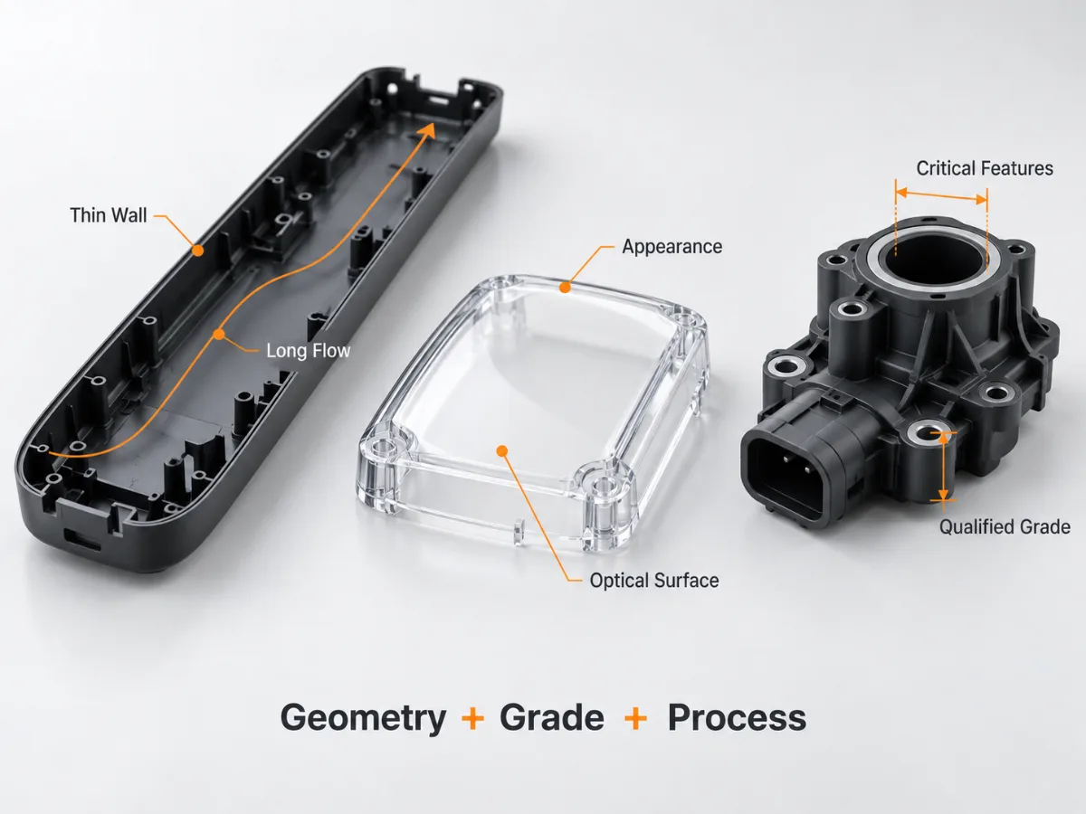
Everything above assumes a part with unremarkable geometry. Three situations compress the usable range further, and each one changes where inside it you can actually run.
- Thin walls and long flow paths. Only the upper part of the range is usable, because the melt has to stay fluid until the cavity is full. A mold flow analysis can show whether the selected grade and process settings are likely to fill the geometry before it freezes.
- Appearance and optical parts. The window is squeezed by mold temperature and surface requirements at the same time, so melt temperature on its own does not tell you much.
- Parts with certification or secondary operations. The acceptable grades narrow first, and the range has to be reconfirmed against the grade you actually qualify.
In these cases, getting the window confirmed against your drawing and your grade costs less than discovering it during the first trial. The injection molding team checks material choice, wall sections and flow length together, before a mold is cut. Following the main injection molding design guidelines also helps prevent geometry from narrowing an otherwise workable processing window.
Conclusion
The window a material runs in decides how much process variation the project can absorb, and that shows up in trial rounds and schedule. If your grade sits close to a boundary in the chart above, or if the part has thin walls, long flow paths or appearance requirements, upload your drawing and have the processing window confirmed for your material before tooling is committed.
FAQ

Alex Yu
IDEAL PRO Manufacturing
Factory Direct MFG

Ready to Manufacture?
Get instant pricing & DFM feedback
20+
Years
Expertise
3000+
Parts
Manufactured
99.8%
On-time
Delivery
Trusted by industry leaders